Thursday, November 26, 2009

Engine Transmission in the Chassis

As the cab gets worked over by Jason, I focused on getting the motor and transmission lowered onto the chassis.

I had a problem locating early style big block truck mounts. The ones I did find were outrageously priced. I later found a nice set of tubular mounts on Ebay. The mounts use existing frame holes and were a snap to install. I also picked up a CPP transmission crossmember. It bolts to the lower part of the frame and allows the exhaust to be routed between the frame rails. This is a must for lowered trucks! In place of the old 400 tranny woulb be a 700R4. The new tranny has the benefit of overdrive and was built to hold 550 hp. Between the tranny and motor is a Rev Maxx 3000 RPM stall converter. A great match for the 304HR cam.

The motor was lowered into the chasis as a shortblock without the transmission. I could have joined the two before but decided to wait. The motor went it easy and the motor mounts were a perfect fit.

Before installing the transmission I needed to seat the stall converter. This proved to be a problem. After several hours I gave up. I called Rev Maxx the next day for help. I was told to return the converter to be resplined. Apparently they had a batch of converters get created with oversized input shafts. Drats! I promptly returned the converter and I am currently waiting for its return. In the meantime I put the transmission in place to help support the motor.

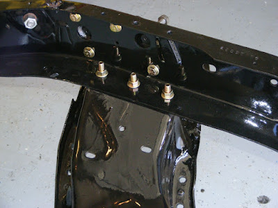
Look at the difference between the stock tranny crossmember on the right versus the new tubular replacement
From Tranny Mount

From Engine and Tranny

The 454 in its final resting place
From Engine and Tranny

Tubular motor mounts
From Engine and Tranny

Body Work Begins at DJ Customs

My newly acquired cab has been lounging in the back of my garage while I focus on getting the engine and tranny in place. Rather than wait to finish, I contacted Jason at DJ Customs in Cedar Park to start on the body work. Jason has years of experience doing custom paint and body along with bagged suspensions.

With the help of my brother Roger, the cab was trailered to DJ Customs. The plan was to have the cab soda blasted to remove any rust, dirt and paint. Jason would then begin the repairs. The inside cab floor and outside bottom would be sprayed with POR15. The rest of the interior with expoxy primer. The outside cab would have all dents removed then get sprayed with expoxy primer.

Here are pics midway thru the work

Before soda blasting
From Cab Work Begins

After soda blasting. Amazing results!
From

Soda blasted firewall
From Cab Work Begins

Blasted firewall
From Cab Work Begins

Interior of cab with floor coated and interior primered
From Cab Work Begins

From Cab Work Begins

Going Full Roller!!

From the very beginning I knew I wanted a roller cam motor. When I purchased the 454 it already came with a nice 292 flat tappet cam. There was no need to change it so I decided to keep it. Once I realized I had to flycut the pistons, I decided to go whole-hog and go full roller. I pulled the Comp 292H cam and replaced it with a very stout Comp 304HR roller cam. The diferrence in duration at .o5o was nominal but the lift in the roller was .612 versus .550 in the 292H. Going roller meant getting roller lifters and a roller timing chain with thrust washer. All Comp Cam products. This added quite a bit more to the cost but got me what I always wanted :)

Comp Ultra Pro Magnum Rockers and Roller Lifters
From Engine and Tranny

Comp 304HR Roller Cam
From Engine and Tranny

Swapping out Cabs

Several posts back I documented the rusts repairs to my 68' cab. I completed most of the passenger side and still had the driver side and firewall to repair. At that time I chose to focus on the suspension and engine work. As I prepared to startup work on the cab, I came across a rust free 70' cab for sale in Waco which is 1 1/2hrs north of Austin. The cab was being offered with the doors and a very nice cab dolley. I knew getting that cab would save me tons of time so I contacted the owner and made a deal. It would be a couple days before I could leave to pick it up. In the meantime I sold my current cab to my friend Calvin. He also took my original long bed. The sale made purchasing the new cab a no-brainer!

Pics of the new cab
From Cab Work Begins
Here you can see the ventilation holes were blocked to smoot the firewall
From Cab Work Begins
Cab corner had been replaced. Nicely done.
From Cab Work Begins

Flycutting Time!!

I will begin by saying I didn't take any pics during the flycutting process. Mainly because it was a very labor intensive process. In hindsight I hate that I failed to document the work. I'm sure others would have benefitted from my experience.

Total time from start to end took a good 9 hrs. The first piston took the longest. From there you have a bench mark for completing the others. I got a little faster with each piston. On piston number 6 I bent the cutting shaft and nearly trashed a piston. I called Dave and he promptly send out a new shaft free of charge.

A week later I was back to cutting pistons. It didn't take me long to cut the final 3 pistons. Boy was I happy that was over!! Here is a pic of a finished piston.

From Piston Valve Clearance

Cutting edges were hit with sandpaper to remove sharp edges and prevent stress risers
From Piston Valve Clearance

Lindy Tools In-Head Piston Cutter

Now that I have decided to flycut the pistons I had to get the proper tools to do the job. I needed a cutting tool that can be used while the pistons were still in the block. I heard Isky Cams made such a cutter so I gave them a call. I was suprised to hear they were 3 months on back order! I then turned to Lindy Tools in Waukegan, IL. They produce an in-head cutter that creates both dept and radial clearance and is superior to the Isky cutter.

When I called Lindy I was suprised the owner, Dave, answered the phone. I explained what I needed and he assured me he had the proper cutter. He also gave me some history around the Isky cutter and why they were not available. At the time I was unsure but felt I had no other choice. I ordered his cutter for half the price of the Isky one.

The Lindy cutters are made to order so it took two weeks to arrive. When it came in I was impressed with the quality of the cutter. Happy with my purchase I started laying out plans to cut the pistons. The process would take over eight hours to complete so I wanted to have everthing right.

Lindy Tools Cutter Size 2.375
From Piston Valve Clearance

From Piston Valve Clearance

Checking Piston/Valve Clearance..We got issues!

A popular method of checking piston/valve clearance is to use modeling clay. It's a simple test but requires the correct parts/tools to get it done right. Details of how to perform the test can be found here: Piston/Valve Check

The results of my test(s) showed I had plenty of depth clearance but my radial clearance was little tight. Too tight for comfort. That left me two options. Replace the pistons or have them flycut open up the valve reliefs. New pistons are expensive and require a lot of work to install. I opted for the flycut. Details of the process will be posted.

A photo of the intake relief with clay
From Piston Valve Clearance

Another after rotating the engine. As you can see the clay was scraped down to the metal.
From Piston Valve Clearance

Wednesday, November 25, 2009

Engine Update: 396 to 454

Finally an engine update! For starters, the original 396 engine was sold on Craigslist. In its place was a rebuilt shortblock 396 that I found in Dallas. After much thought I decided the 396 was not going to be enough so it was also sold on Craigslist. I then picked up a very nice rebuilt shortblock 454. This block came bored .030 over with Speed-Pro pistons and Comp Cams 292H camshaft.

Rebuilt 396 on the left and 454 on the right.
From Engine and Tranny

For cylinder heads I chose Edelbrock's Aluminum Performer RPM Marine heads. They come with large 2.25 intake valves and 1.89 exhaust valves. The heads came bare and were later fitted with Comp Cam 924-16 valve springs. All work was performed by Austin Performance.

The head/piston combo gives me a compression ratio of 10:1 which was my target. Next step was checking piston/valve clearance.

45 Days of Brakes!!

Brakes are supposed to be easy. That statement is mostly true if you have all the correct parts. I did not.

Since there was no way I was going to put dirty brake lines on my refished chassis, I opted for a preformed kit from Inlinebrakes.com. The replacement lines are stainless steel and look trick. I ordered their 68' conversion kit for a shortbed truck.

When I tried to lay the lines I found they sent me a longbed kit. The front to rear line was way too long. The rear differential lines were also different.

Here you can see the line goes past the connection
From Inlinetube 68' Conversion Lines

In this photo you can see the lines don't bend forward to the t-block.
From Inlinetube 68' Conversion Lines

It literally took weeks of back and forth emailing and returning of products to get all the issues worked out. Not all the problems where the fault of Inlinetube. My local autoparts gave me one wrong brake caliper. It was in the correct box but was the wrong product. It fit great but the lines didn't fit. By this time I had already painted it red! They allowed me to return the red caliper in exchange for a correct replacement. Overall it took a good 45 days to work out all the issues.
The corrected rear lines:
From Inlinetube 68' Conversion Lines

Correct front-to-rear line. Crossmember was not complete in this photo
From Inlinetube 68' Conversion Lines

Finally got the wheels back on
From Inlinetube 68' Conversion Lines

Moving right along..

It's been a while since my last update and a lot has been done. Before I post the new changes, I need to update work on the chassis. After my previous posting, some errors were pointed out by my pals at 67-72chevytrucks.com. I spent the next weekend making the following corrections: Upper ball joint location and rear upper shock mount orientation. Took a few hours but it's all good now.

Monday, August 31, 2009

Rebuilding the SWB chassis

Major teardown is finally complete! Now I can start putting her back together. It began from the ground up starting with the new chassis. The old long bed chassis was carried out of the garage and placed on the side of the house. This made a huge amount of room in the garage.
From SWB Chassis Rebuild

Next I placed the new short bed frame in the center of the garage and started reassembling the suspension. I started with the rear by adding several new components. All from my Early Classic Enterprises 4/6 drop kit. It drops the truck 4" in the front and 6" in the rear. I added shock mount relocators and relocated the track bar to the right trailing arm.
From SWB Chassis Rebuild

I then bolted the crossmember onto the short frame. It was a perfect fit! Everything lined up nicely.
From SWB Chassis Rebuild

Next I replaced the upper and lower control arm shafts and ball joints. This by far was the hardest part of the suspension rebuild. It was kinda like that move "A Christmas Story". Remember the dad fighting with the furnace, cussing and yelling? That was me! With the shafts in place I could begin reassembling the front suspension. The old spindles were replaced with ECE 2 1/2" drop spindles. I used ECE 1 1/2" drop springs, all new grade 8 nuts and bolts, new brake rotors and calipers. When I finally got it all togther, I stepped back, lit up a cigar and admired my little masterpiece :)
From SWB Chassis Rebuild

Passenger Side:
From SWB Chassis Rebuild

A little elbow grease goes a long way!
From SWB Chassis Rebuild

Drivers sideview:
From SWB Chassis Rebuild

Slideshow of photos. The old rear cover looks out of place. It gets replaced later :)

Clean and Paint

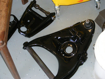
Now it was time for the real fun. Cleaning years of grease and dirt off the suspension components. I used an electric drill, several stripping pads and wire wheels to clean up the rear differential and front control arms. It was a messy job and took a few hours over. Afer cleaning, I wiped everything down with thinnner then painted the parts with POR15. Here is a photo of the control arms after cleanup and paint. The old shafts were later replaced.
From SWB Chassis Rebuild
:

Front Suspension Removal

Now that the motor and transmission have been removed, I started stripping down the old LWB chassis. Before I did anything, I took photos detailing the layout. All 53 photos can be seen here.
I started by removing the brake/fuel lines and emergency brake cable. I then went to work on the front crossmember. An engine hoist was used to support the chassis while the crossmember was unbolted from the frame. A floor jack was used to support the crossmember. I did my best to keep it from slipping off the jack. It eventually did but caused no harm.
From Front suspension removal

With the crossmember was separated from the frame, I started dismantling the front suspension. This posed a problem. Front coil springs are under high tension and can be very dangerous if not removed correctly. Typically the motor and transmission provide enough weight to allow compressing the spring with a floor jack positioned beneath the control arm. With no motor and tranny, I had no weight to compress the spring. After asking questions online I decided to cut the springs with a cutting wheel. It was a little scary cutting thru that first spring. When it finally broke it did so with a very loud, POP! Scared the crap out of me!
From Front suspension removal

Eventually I got everything loose then dismantled the rear suspension which way easier than the front. Here are photos:

Thursday, April 16, 2009

Engine and Tranny Removal

This was by far the easiest motor/tranny removal I have ever done. Of course that's not counting the work to remove the cab and front clip. All I had to do was position the hoist, attach the load leveler, and lift out the motor and tranny as a single unit. I highly recommend using a load leveler when doing this type of work. It allows you to change the center of gravity to keep everything level. Without it, you end of with a pool of tranny fluid on the floor of your garage. Once I had the motor/tranny free from the chassis, I lowered the tranny to rest on the leg of the hoist. I then unbolted the tranny from the motor while balancing it on the hoist. I slid it to the side once it was free. Btw, I made sure to unbolt the torque converter from the flywheel while the motor and tranny were still on the chasis. Next I bolted the engine stand to the motor and lowered it to the floor. I then removed the load leveler and pushed the hoist out of the way so I could begin tearing down the motor. It didn't take long to tear the motor down to a bare block. In doing so I found the #1 cylinder had spun a bearing which explained the knock. Next step is to find a good engine shop here in Austin and have the block prep'd for rebuild.

Tuesday, April 7, 2009

Cab Removal Time!!

With the passenger side rocker complete, I decided to remove the cab to make room for the chassis and motor work. Those two items are the biggest part of the LWB to SWB conversion. The mounted cab prevented me from making any real progress on the chassis. With it removed, I can work on all three.

All the work is happening in my two car garage since my neighborhood HOA forbids working in the driveway. The garage has two separate doors. One side has an opener which sits too low to lift the cab. That confined me to the other side. After thinking it thru I came up with the following plan. At this point the cab is bare except for the empty gas tank. I heard the cab was front heavy so I left it in place. I doubt it made much of a difference.

First I built a cab dolly out of 2x4's. Cost$65. I considered welding a steel frame but felt it was overkill for something I'd use once.

Next I positioned my lift between the wall and cab then setup a 4x4 on wood blocks left over from the cab dolly. I made sure to position the 4x4 as far forward as possible.

With the cab bolted down, I raised the 4x4 to the cab to see where to cut the notches. I used a sawzall to make the cuts.

I then unbolted the four cab bolts and slowly lifted the cab. As the cab came up I expected it to tilt forward but it stayed level. The cab is suprisingly light. Only about 300 lbs.

Once the cab was high enough, I pushed the LWB chassis sideways until it cleared the cab. Tireskates made this easy. I then lowered the cab onto the dolly.

Once the cab was on the dolly, I moved it into the corner of the garage. That gave me enough room to angle the chassis back in place and prepare to remove the engine and tranny.

Rocker Replacement Part 2

So it's been quite a while since my last post and a lot has happen. For the most part the passenger side rocker panel is complete. I still have some finish grinding and a couple small floor holes to weld up.

When I left off in part 1, I had just finished removing the rocker panel. The metal underneath had some serious surface rust. I grinded away the surface rust and painted it with POR15.

Next I made my first there-is-no-going-back cut. I cut off the rusted A-pillar just above the lower door hinge bolt holes. I then cut out the inner kick panel. In the photo below you can also see where I welded in my first floor patch.


With the floor patch in place, I then welded in the new kick panel. It was a bitch getting it to align with the bottom shape of the floor. Mainly due to the shape of the floor patch. I ended up removing the first floor patch and redoing it a couple times before I was satisfied with the work. Sorry I don't have photos of the kick panel prior to installing the A-pillar. I then took the replacement a-pillar, bolted it in place, scribed a cut line, then cut it to fit and welded it in place. As you can see there is a big improvement of the rusted out piece.


Next I mounted the new rocker panel using sheet metal screws. Then one-by-one, I removed each screw and plug welded the hole. When I was done I grinded down the welds.

Tuesday, January 6, 2009

Finally Found a Fleetside Short Box!!

Due to the holidays not much as happened on the 68'. Plus I needed a mig welder. Also it would be nice to know how to weld :) I heard it has a short learning curve. Just takes some guidance and practice. I'll find out soon enough, yesterday I picked up a Hobart Handler 210. Based on reviews it's a great little mig welder. It's a 230 volt model which means I need a 230v plug installed in the garage. I just started looking for an electrician do the install. I hope to have it in place by the weekend.

In other news I finally found a fleetside short box!! It took 2 months to find one. I was just about to give up and see about getting the long bed cut down. Not something I wanted to do so it was a good find. I did not have my camera when it was delivered so no pictures. I hope to get some up soon.